

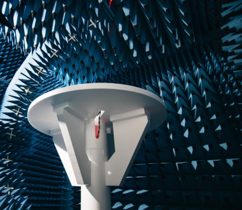
SISO Passive Wireless Measurement Chamber
Our Over-The-Air (OTA) Chamber enables real-world RF and antenna performance validation for Wi-Fi, Bluetooth, IoT, and proprietary wireless products.
It is specifically optimized for rapid design verification, troubleshooting, and pre-compliance evaluation during ODM R&D, EVT (Engineering Validation Test), and DVT (Design Validation Test) development cycles.
Supported Wireless Technologies
Custom Antenna Designs Supported:
- PCB Trace Antennas
- Flexible Printed Circuit (FPC) Antennas
- Monopole & Dipole Antennas
- Chip Antennas
- External & Whip Antennas
Reference Standards & Guidance
Conducted per engineering evaluation guidelines referencing international test methodologies:
- FCC Part 15: Radiated Emissions engineering reference
- CE / ETSI RED: EN 300 328 & EN 301 893 reference
- Industry OTA Methods: Standard SISO passive radiated testing methodologies
What We Can Test:
- Wireless signal strength (OTA power & sensitivity)
- Real Wi-Fi / Bluetooth range & connection stability
- Verify antenna performance after product assembly (good / bad / blocked)
- Impact of enclosure plastics, battery, metallic shielding & LCD parts
- Direct benchmark comparison of old vs. new design or competitor devices
- De-risk designs before entering costly formal certification labs
1. Radiated RF Performance
- Radiated Output Power (EIRP / TRP-like SISO)
- Radiated Sensitivity / RSSI Testing
- Link budget & margin verification
- Signal strength mapping vs. orientation
- Orientation sensitivity analysis (X / Y / Z axes)
2. Antenna Characterization & Debug
- 2D Radiation Patterns (Azimuth & Elevation planes)
- 3D Antenna Radiation Pattern Visualizations
- Peak & Average Antenna Gain
- Radiation Efficiency (relative & comparative)
- Polarization analysis
- Null & lobe identification
- Antenna placement impact study
3. Frequency & Bandwidth Analysis
- Wide frequency sweeps
- Resonance shift & detuning detection
- Multi-band antenna verification
- Impact of housing, cabling, battery, LCD & shielding
- Before vs. after design comparison
4. Comparative & Competitive Testing
- Golden sample vs. new design verification
- Antenna A vs. Antenna B side-by-side comparison
- Competitor device performance benchmarking
- Design iteration validation
Wi-Fi Products
- Orientation & 360° rotation testing
- 2D & 3D Antenna radiation patterns
- Dead-zone & blind spot checks
Bluetooth & BLE Devices
- Connection stability & receiver sensitivity
- Hand / body proximity effect analysis
- Short-range reliability check
IoT & ISM Devices
- Sub-GHz & 2.4 GHz antenna tuning
- Long-range link margin verification
- Battery & sensor enclosure impact evaluation
Example Measurements Provided
- Antenna 2D / 3D Radiation Pattern Plots
- Wi-Fi / BT RSSI & Signal Strength Mapping
- Frequency Sweep & Gain Plots
Common RF Issues Diagnosed & Fixed
- Poor Wi-Fi range or weak transmission coverage
- Frequent Bluetooth connection drops and pairing failures
- Orientation-dependent link failures (device angle loss)
- Low RSSI signal strength despite good conducted output power
- Antenna detuning caused by enclosure assembly and plastics
- Metal shielding, battery, or PCB trace interference
- Ground clearance limitations & RF matching circuit issues
Comprehensive Engineering Test Report
- Test Summary & Plots: Full measurement summaries and performance charts.
- Radiation Pattern Images: High-resolution 2D (polar) and 3D radiation plots.
- Gain & Frequency Sweep Charts: Accurate frequency response curves and peak gain figures.
- Engineering Observations & Recommendations: Practical design feedback from experienced RF engineers to optimize performance.

Use our OTA results to reduce product risk, cut down re-test cycles, and lower overall lab costs before going to accredited FCC / CE certification labs.
Inquiries & Test Bookings
If you would like to learn more, discuss your wireless project, or schedule an OTA test session, please contact our RF engineering team:
John See: johnsee@qavtech.com
H.S. Tham: hstham@qavtech.com